
")
Step 4: Connecting cable harness with the fuse box
Fundamental: Remove the keys from the car and then remove the one pole of the battery.

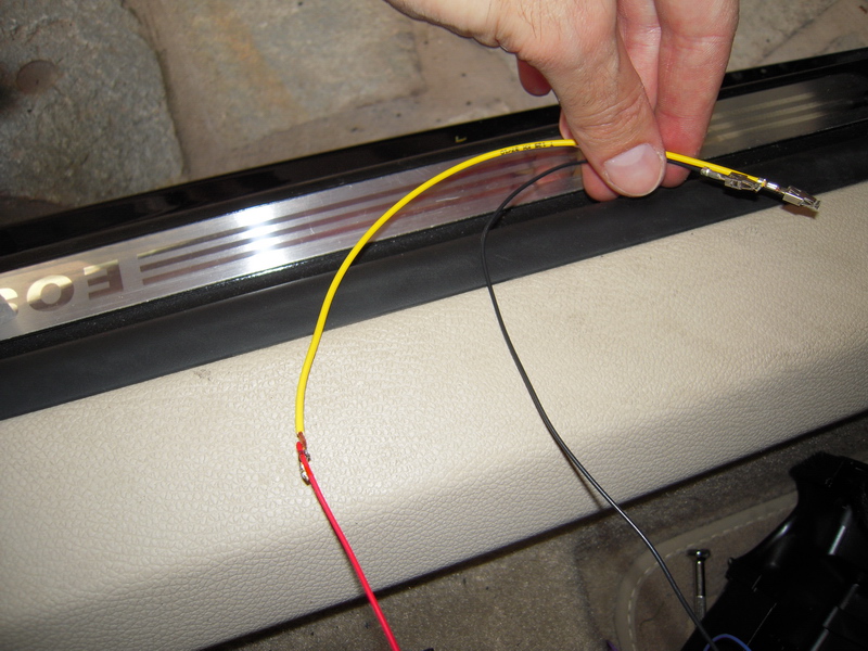
The most right way to get the necessary power for the sensor and the mirror is from the fusebox. The fuse box gives 12V voltage, at some points interrupted, ie it does not give power when the machine is not working, in other places it gives power when the key is in the starter and in others it gives continuity (continuous). The wiring is almost ready to get power from the fuse block. And we say almost because the mirror wire that goes into the fuse box does not have the special plug that snaps into the fuse box. Here we use the yellow cable, which has this special slot. So cut the yellow wire as below.

Turn the wires together and seal them by trying to make the union as small as possible. Make sure you put the protective plastic piece before the joints. If you do not have a protective plastic piece, you can use an insulating tape.
The following picture shows the cables after we have soldered it together.
Then remove the light switch by pushing it in when it is in position 0 and turning it towards the On position. This will unlock it.


Remove the torx screw, which is hidden on the upper side.

Remove the plastic steering wheel cover by pulling the two edges towards you and then unscrew the left screw, which can be shown below.

Remove the small glove compartment located on the driver's side. This is done by opening it and pushing together the two sides at the back.
Unscrew the screw at the top.


And then unscrew the other two screws on the bottom.


Unclip the plastic side of the guide with the plastic removal tools and see the fuse box.
Unscrew the screws at the top and bottom of the fuse block and then the fuse block comes out of position.
Carefully remove the three clips that hold the fuse block.


The next step requires removing all fuses. You photograph them carefully to know their positions.


The mirror and sensor connectors, their respective wires and the positions to which they are connected are as follows:
Mirror Connector (1C0-973-119 B):
Pin 1: +12V, 5Α. Interrupted power supply (black cable, thick plug cable).
Pin 2: Ground (brown wire).
Pin 3: In the ECU - brain, connect to position cable B1, to identify reverse (blue cable).
Pin 4: To the driver door controller for the anti-glare function of the exterior. mirror (yellow cable).
Pin 5: To the driver door controller for the anti-glare function of the exterior. mirror (blue-yellow cable).
Pin 6: To the ceiling - Dome light (green cable that has the small plug)
Sensor Connector (4B0-971-833):
Pin 1: +12V, 5Α. DC power supply (red cable).
Pin 2: Ground (brown wire).
Pin 3: At the brain - ECU, position F3 (violet cable).


In the above figure, the plugs with the multiple wires snap into the mirror socket and the other plug in the sensor socket. Caution: Both plugs are clamped off only by a special tool.
According to the user manual (page 110), the light-rain sensor fuse in position 13 is red and 10 ampere. The fuse for the internal mirror with automatic anti-glare function locks in position 4 and is light brown and 5 ampere.
However, because the positions were covered by other insurances, you have to choose similar ones. Be careful that the posts have contact at the top otherwise they will not go there. In our case, the black cable (mirror) with the ready coarse plug will be connected to position 6, while the yellow cable we made (the sensor) will be connected to position 17, as you can see in the figure below.

Remove the rear plastic part of the fuselage. With a thin, straight screwdriver, unwrap the plastic plate and with the other hand push the purple piece to unlock the sockets. A click click will be heard.


Now insert the wires into the correct sockets. They are numbered, so find the number that says 6 and enter the mirror black cable in the bottom position. Proceed, respectively, for the red sensor cable that comes under the number 17. They come in very easily, and sounds like a sound when they snap into the socket. You should pay close attention to getting in because if they are wrong, they only come out with a special removal tool.
The next step is grounding. The right way to get ground and have no problems is from the central point of grounding behind the bonnet opening lever. Then pull the lever out, remove the cap from the screw, unscrew it with a straight screwdriver, and then unbuckle the lever cap by using the screwdriver (see the pictures below for help).


Then remove the plastic piece and see the ground point. Unscrew the screw, put the ground, screw it back and do it after the reverse procedure.


After assembling everything as it used to be before, the fusebox will look something like this:
