
")
Difficulty level: High
Total Time Required: 12 Hours
In this DIY, we present you the installation of lights and sights package in a VW EOS car. The retrofit of auto-folding mirrors is described in another DIY due to cost, time and difficulty.
This packet includes an internal and an external mirror which have a light-sensitive automatic mechanism1 (auto-dimming), a side-view mirror which dips to assist reverse parking 2, "Coming home"3 and "Leaving home"4 functions, rain sensor5 and light sensor6. Also, the side mirrors are power folding7 and they have a perimetric lighting system8.
In the following guide, we try to present the installation of this packet to a Volkswagen EOS car.


1: The mirrors dim automatically if a car has ON its high beam headlights or its headlights are not correctly adjusted.
2: Co-driver's side mirror is adjusted such as it changes position automatically in order to assist reverse parking, so the pavement is visible by the driver.
3: By unlocking the car, the car lights open for an X desired time. The light sensor triggers the lights only in law light conditions.
4: By locking the car, the car lights open for an Y desired time if the driver activates the process.
5: The rain sensor activates automatically the windscreen wipers and regulates their speed according to the amount of rain. Also, it closes automatically any opened windows and the sunroof, provided the function "auto rain closure" is already enabled.
6: The light sensor enables the headlights under low light conditions.
7: The side mirrors fold and unfold automatically using a switch.
8: The perimetric lighting system is triggered by the functions "Coming home"3 και "Leaving home"4.
A popup will display, which you can close and then you will be able to read the article.
YOU MUST DISABLE IT, IN ORDER TO BE ABLE TO READ THE REST OF THE ARTICLE.

VW Lights & Sights
Step 1: Gathering necessary equipment
What is needed
- New Rain-Light Sensor (1K0 955 559 AH): 60€ + 10€ shipping -> 70€

- Auto-dimming mirror (1K0 857 511 B 9B9): 50 €

- Cable Harness - Kabelsatz Regensensor +Abb VW: $38.58 + 10€ shipping. -> 39 €

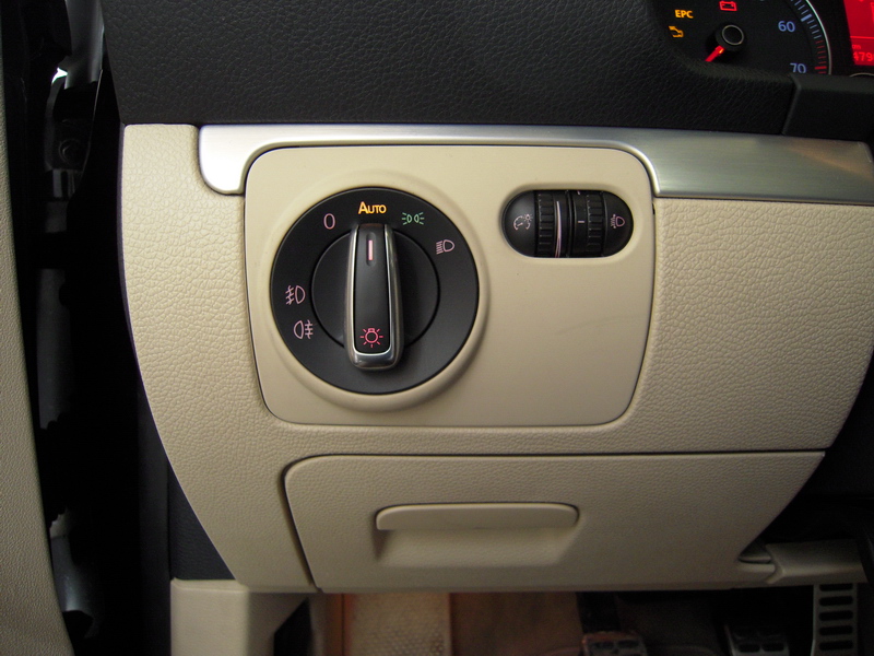
- Chrome Head Light Switch AUTO: $35 incl. shipping -> 25 €
This switch, apart from nikel, has orange color at auto position, green color at headlights position and red color at the rest positions.
- Plastic covers for the sensor (1Q0 857 594 9B9 + 1Q0 857 593 9B9): 15 €

- Mirror plastic covers (1K0 858 547 9B9 + 1K0 858 548 9B9): 6 €

- Plastic roof cover with a small hole - optional - (1K5 857 304 9B9)
It is NOT required at a VW EOS.
- Big plastic roof cover with a hole (1Q0 867 390N 82V)
- optional - recommended to buy: 45€
- Windshield (green) with rain-light sensor socket (1Q0 845 011 AJ): 370 € + 100 € labor: 470 €

Please be advised that the windshield may take a while to ship in your location.
- Yellow cable with part number 000-979-133 for ECU connection: 1 €
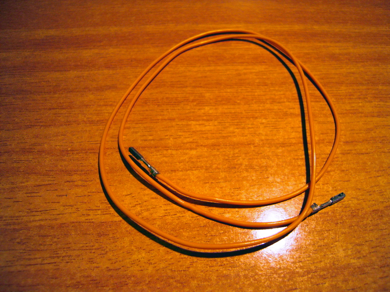
- Yellow cable with part number 000-979-009 for fusebox connection: 1 €
- Two small 5 Ampere fuses with light brown color: 1 €

Attention: Please be advised that there are larger 5 Ampere fuses that won't fit in your fusebox.
NECESSARY TOOLS
- Torx screwdriver of size T20 and T18.


- Trim Removers.

- Special drill tool for opening the hole for the sensor and mirror cables (it is only needed if you won't replace the big plastic roof cover): 30€

- Optical Power Meter (optional: for checking the integrity of cable harness)
- Cutter.
- Insulation tape.
- Tyre Ups.
- Soldering iron and solder.
- Laptop having VCDS software pre-installed along with a special Vag-Com cable.
NOTICE
You must gather all the equipment - tools and read this DIY guide before you begin this project.
This DIY is specifically made for VW EOS cars. The equipment, cable harness and/or connections may be differect in your car.
We will not be held responsible for any damage which may happen to your car by following this guide.
Step 2: Wiring installation - Removing the roof plastic cover
You must remove the big plastic roof cover in order to make the necessary modifications. This procedure is not too hard but it should be done with caution.
First we remove the ceiling. Remove the decorative plastic with a credit card that we insert into the slot of the ceiling and then lightly push the two clips that are underneath, remove the ceiling. Remove the power and microphone cables.
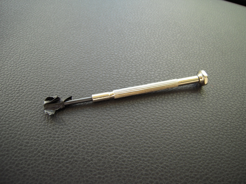
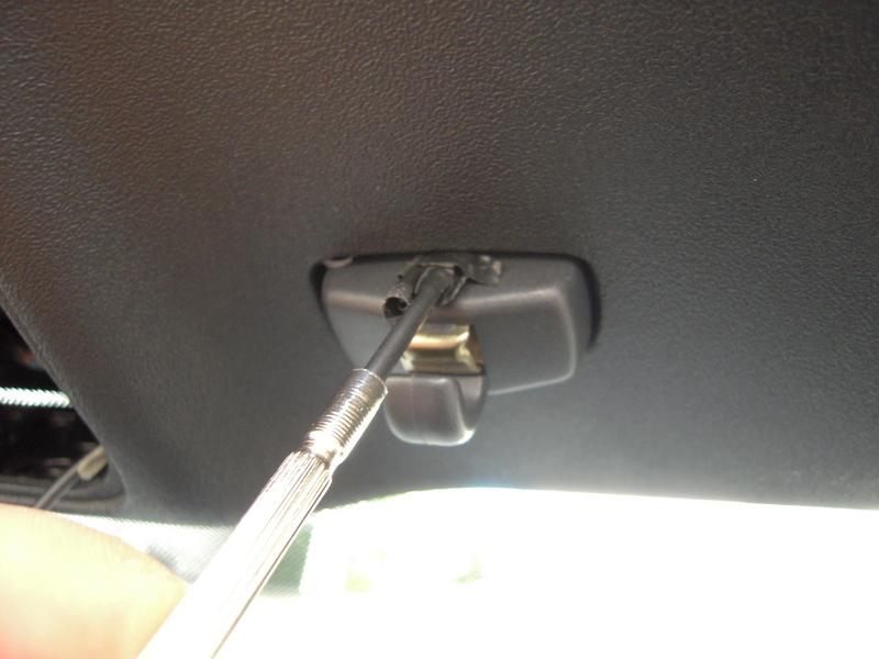
Then we have to remove the driver's and passenger's sun visors. We start with that of the co-driver. We unbutton with a small straight screwdriver, to which we have applied an insulating tape, the plastic cap to reveal the torx screw and unscrew it.
We take the plastic of the shade a little to our side, and when the power cord is unveiled, we take it out of the socket.
We remove the sun visor and perform the same procedure for the driver's sun shade.
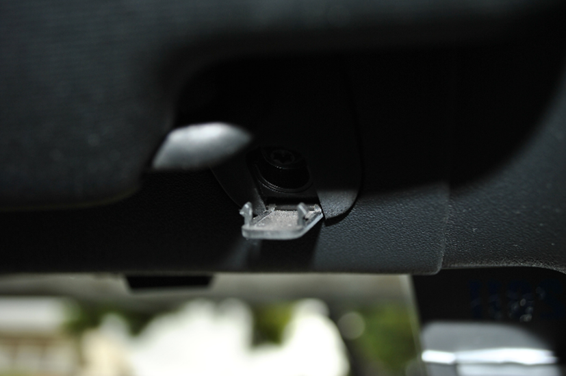
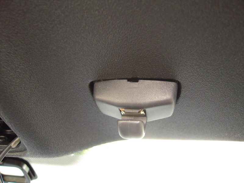
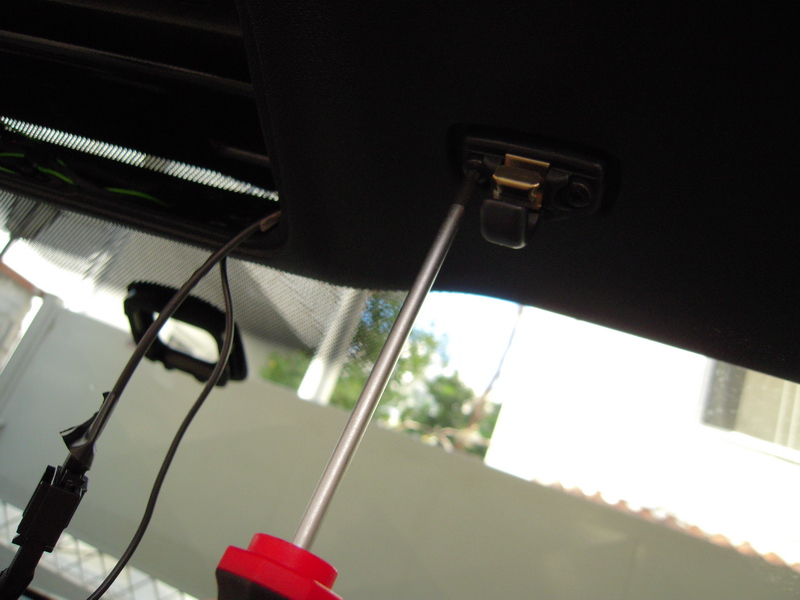
There are two plastic clips that fix the shades. Here, we must carefully insert a thin straight screwdriver right between each clip and the top of the roof and move the plastic cover of the clip down.
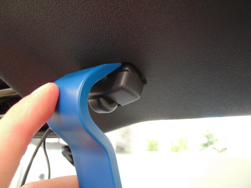
As soon as the plastic lid comes down, remove it with the special tool for the plastic parts and then unscrew the two torx screws that are hidden beneath the clips.
We can now remove the big plastic roof cover.
After the big part of the roof comes out we pull out the driver's column and pass the wiring. The ready plugs go to the mirror and the sensor and the rest in the fuse box. We make sure we get the wiring harnesses where there is already factory wiring and of course there is no chance of being caught by the plastic when we click on it.
At this point, you either have to replace the big part of the roof or drill the existing one.
Step 3: Modifying / Replacing the big plastic roof cover
Modifying the existing big plastic roof cover
The big part of the roof has a mark in the center, where we have to make a small hole with a suitable multi-tool-drill from which the cables will pass.

Replacing the big plastic roof cover
The big part of the roof, which has the hole for the cabling ready, has a part number of 1Q0 867 390N 82V and is priced around 45 euros. At first we had formed the existing piece of the roof, but unfortunately this way the sensor did not work properly as it did not fit properly.
As a better solution, therefore, it is proposed to replace the large part of the roof.
Step 4: Connecting cable harness with the fuse box
Fundamental: Remove the keys from the car and then remove the one pole of the battery.

The most right way to get the necessary power for the sensor and the mirror is from the fusebox. The fuse box gives 12V voltage, at some points interrupted, ie it does not give power when the machine is not working, in other places it gives power when the key is in the starter and in others it gives continuity (continuous). The wiring is almost ready to get power from the fuse block. And we say almost because the mirror wire that goes into the fuse box does not have the special plug that snaps into the fuse box. Here we use the yellow cable, which has this special slot. So cut the yellow wire as below.

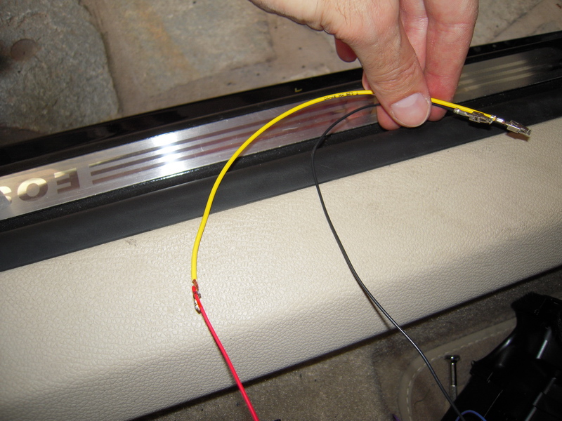
Turn the wires together and seal them by trying to make the union as small as possible. Make sure you put the protective plastic piece before the joints. If you do not have a protective plastic piece, you can use an insulating tape.
The following picture shows the cables after we have soldered it together.
Then remove the light switch by pushing it in when it is in position 0 and turning it towards the On position. This will unlock it.


Remove the torx screw, which is hidden on the upper side.

Remove the plastic steering wheel cover by pulling the two edges towards you and then unscrew the left screw, which can be shown below.

Remove the small glove compartment located on the driver's side. This is done by opening it and pushing together the two sides at the back.
Unscrew the screw at the top.


And then unscrew the other two screws on the bottom.


Unclip the plastic side of the guide with the plastic removal tools and see the fuse box.
Unscrew the screws at the top and bottom of the fuse block and then the fuse block comes out of position.
Carefully remove the three clips that hold the fuse block.


The next step requires removing all fuses. You photograph them carefully to know their positions.


The mirror and sensor connectors, their respective wires and the positions to which they are connected are as follows:
Mirror Connector (1C0-973-119 B):
Pin 1: +12V, 5Α. Interrupted power supply (black cable, thick plug cable).
Pin 2: Ground (brown wire).
Pin 3: In the ECU - brain, connect to position cable B1, to identify reverse (blue cable).
Pin 4: To the driver door controller for the anti-glare function of the exterior. mirror (yellow cable).
Pin 5: To the driver door controller for the anti-glare function of the exterior. mirror (blue-yellow cable).
Pin 6: To the ceiling - Dome light (green cable that has the small plug)
Sensor Connector (4B0-971-833):
Pin 1: +12V, 5Α. DC power supply (red cable).
Pin 2: Ground (brown wire).
Pin 3: At the brain - ECU, position F3 (violet cable).


In the above figure, the plugs with the multiple wires snap into the mirror socket and the other plug in the sensor socket. Caution: Both plugs are clamped off only by a special tool.
According to the user manual (page 110), the light-rain sensor fuse in position 13 is red and 10 ampere. The fuse for the internal mirror with automatic anti-glare function locks in position 4 and is light brown and 5 ampere.
However, because the positions were covered by other insurances, you have to choose similar ones. Be careful that the posts have contact at the top otherwise they will not go there. In our case, the black cable (mirror) with the ready coarse plug will be connected to position 6, while the yellow cable we made (the sensor) will be connected to position 17, as you can see in the figure below.

Remove the rear plastic part of the fuselage. With a thin, straight screwdriver, unwrap the plastic plate and with the other hand push the purple piece to unlock the sockets. A click click will be heard.


Now insert the wires into the correct sockets. They are numbered, so find the number that says 6 and enter the mirror black cable in the bottom position. Proceed, respectively, for the red sensor cable that comes under the number 17. They come in very easily, and sounds like a sound when they snap into the socket. You should pay close attention to getting in because if they are wrong, they only come out with a special removal tool.
The next step is grounding. The right way to get ground and have no problems is from the central point of grounding behind the bonnet opening lever. Then pull the lever out, remove the cap from the screw, unscrew it with a straight screwdriver, and then unbuckle the lever cap by using the screwdriver (see the pictures below for help).


Then remove the plastic piece and see the ground point. Unscrew the screw, put the ground, screw it back and do it after the reverse procedure.


After assembling everything as it used to be before, the fusebox will look something like this:

Step 5: Connecting cable harness with the car brain – ECU (Electronics Control Module)
The ECU is located above the driver's paddle on the left. Unscrew the two screws and remove the plastic cover. The job is quite awkward and difficult, so get ready for acrobatics!


Below you can see ECU reception positions.
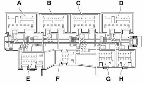

Lightly pull the red plastic to the right to unlock the slots. There is an AUF mark -> there.

Then unclip the B1 and F3 positions by pressing the corresponding clips. The violet sensor cable fits into position F3, in which there is a violet-white color cable, and the blue cable goes to the B1 position of the brain to identify the reversion, in which there is a blue-black color cable. Because the seats are down, you need to strip the cables a little, and then connect them with the cables in the correct sockets.
Finally, with the soldering iron melt a little bit of the cloth on the joints and, once you put an insulating tape, you grab both cables with a tie so they do not hang.

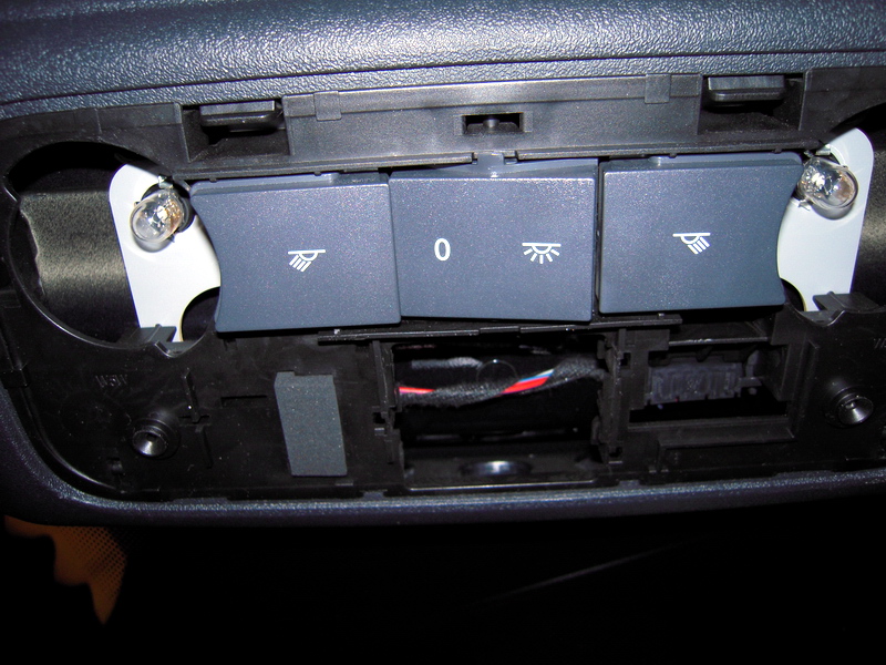
Step 6: Connecting the cable harness with the dome light
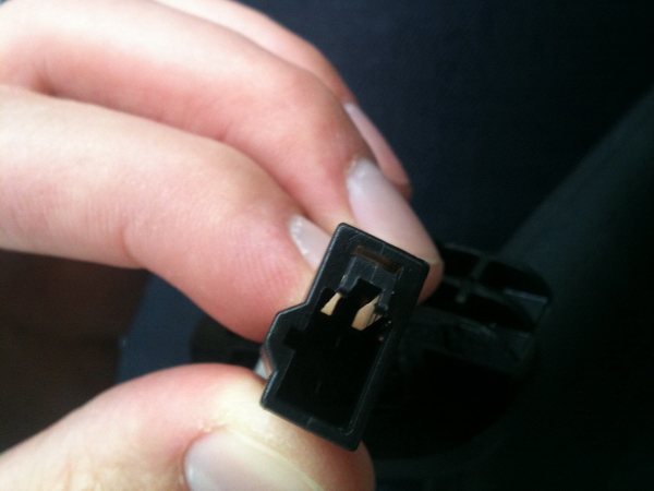
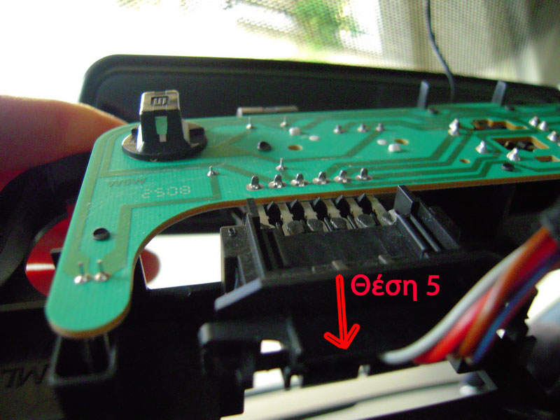
The green cable, which is close to the ready plugs, is connected in the middle of the central veneer so that when the light opens the mirror does not turn black. The plug that it has is not correct, so you will need the yellow cable with part number 000-979-009. Otherwise, you can modify the existing plug but this is not recommended. The free positions of the ceiling lamp plug are two: 5 and 6. The cable must be in position 5, as shown below, because if you follow the path on the board, you will see how it connects to the lamps.

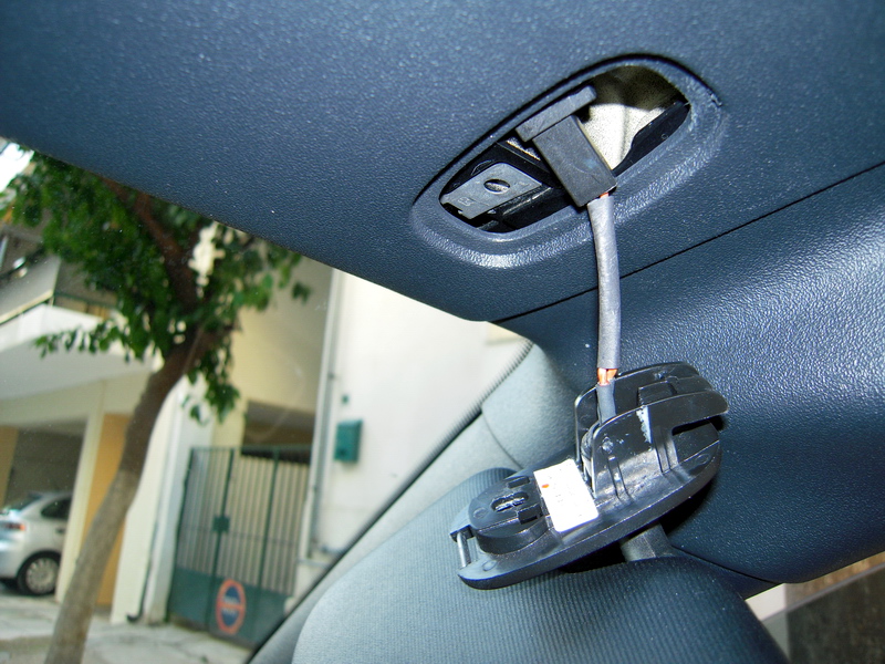
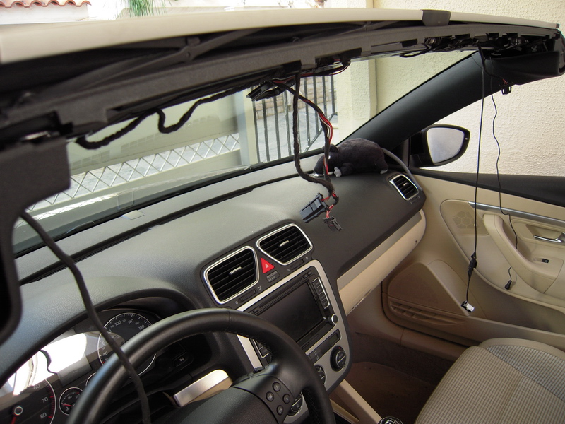
The figure below shows the green cable connected to the ceiling and the rain-light sensor connected to the wiring.

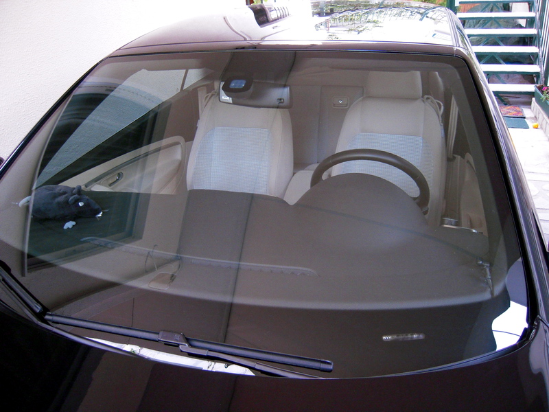
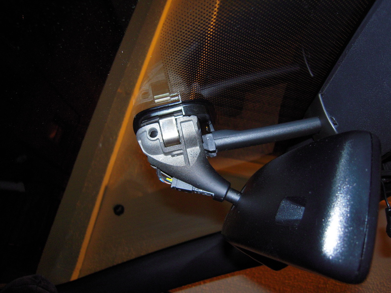
Step 7: Retrofit sensor and mirror
Before connecting the sensor and the mirror, the jelly mount of the sensor must be checked, which must be clean and there should be no air gaps between the base and the windscreen. The sensor fits into the base on the windscreen and the mirror sits on it. The plastics are plugged from above.


Step 8: Coding with VAG-COM
Now connect the battery pole and put the car forward. There will be several errors, do not panic. Put the car in the wild and open the vcds.
Function Coming - Leaving Home
Through this automation, the lights are turned on for an X desired interval when you unlock the car in low light conditions and it is also possible to open the lights for a desired Y interval when you lock the car to safely move away.
Now go to 09-Cent. Elect. and activate the bits 5,6,7:
> 

Then the corresponding options will be displayed on the FIS screen in front of the driver's wheel and you can choose more settings from there.
Auto sunroof and windows closure in the event of rain (Rain Closure)
Through this automation, it is possible to automatically close windows and the sunroof in case the rain sensor detects drops of water. Also, the windows and sunroof are closed after 24 hours that will be open regardless of whether rain is detected or not.
The function is activated only by locking the car and after 2 minutes.
From the main menu of modules select 09 Cent. Elect. and after the list that appears, select the Rain Light Sensor (RLS).

There you check the bits 1-2 and uncheck the bit5.
Bits 3-4 refer to the sensitivity of the lights. In normal mode, they will automatically switch on in the tunnel, in low visibility conditions and of course at night. If you are not satisfied, you can choose more sensitivity, so the lights even turn to cloudy.

Then in bytes 2 and 3 you make choices depending on our car, the type of windscreen and the version of the sensor.
In this guide, the windshield has green glass and the sensor has an AH ending.


You have now turned on the function. What's left is to enable the MFD menu to enable or disable the function at will.
From the main menu, select the 46 Cent module. Conv> Coding - 07> Long Coding Helper.
Byte 09 we select bit1.

This will display an option on the FIS screen to enable / disable the function.
Step 9: Retrofit automatic folding mirrors
Part of the Lights & Sights package is also the automatic reclining driver and front passenger mirrors, which also feature perimeter lighting at the bottom. In addition, the driver's mirror has automatic anti-glare function while the front passenger has a reversing immersion function.
This installation of automatic tilting mirrors is a separate project. Refer to the VW Projects section for detailed information.
Step 10: Final check
Engage the engine and check if all is working properly. To check the mirror, turn on the engine, cover the rear left side of the mirror on which the light sensor is located, and then press the button. It should be "black". Reverse and must be done as before. If you turn on the ceiling, it will have to be normal again.
To test the light sensor (if it is day), turn on the engine, turn the switch to AUTO and cover the point of the sensor with a dark object. The lights should light up
To control the rain sensor, put the windscreen wipers on an operating ladder and see if they stop after one turn or continue to move. They should now only work if the rain sensor detects drops of water. So, you drop water at the point where the sensor is located and must begin operating.
Also, via a vag-com cable, you can select "Meas. Blocks - 08" (located at 09- Cent. Elect) and dropping water on the sensor to see the values being changed.
To check the automatic closing of sunroofs in rain, lower the windows, open the sunroof, lock the car, wait for 2 minutes and pour water on the sensor. You must have the function activated via the display in front of the steering wheel.
Take a ride on the car so the brain can understand that there is no problem and the bugs will be erased on their own.
References
http://www.vwclub.gr/vwforum/index.php?showtopic=27405
http://www.myturbodiesel.com/1000q/multi/rain-sensor-auto-wiper-retrofit-vw.htm